
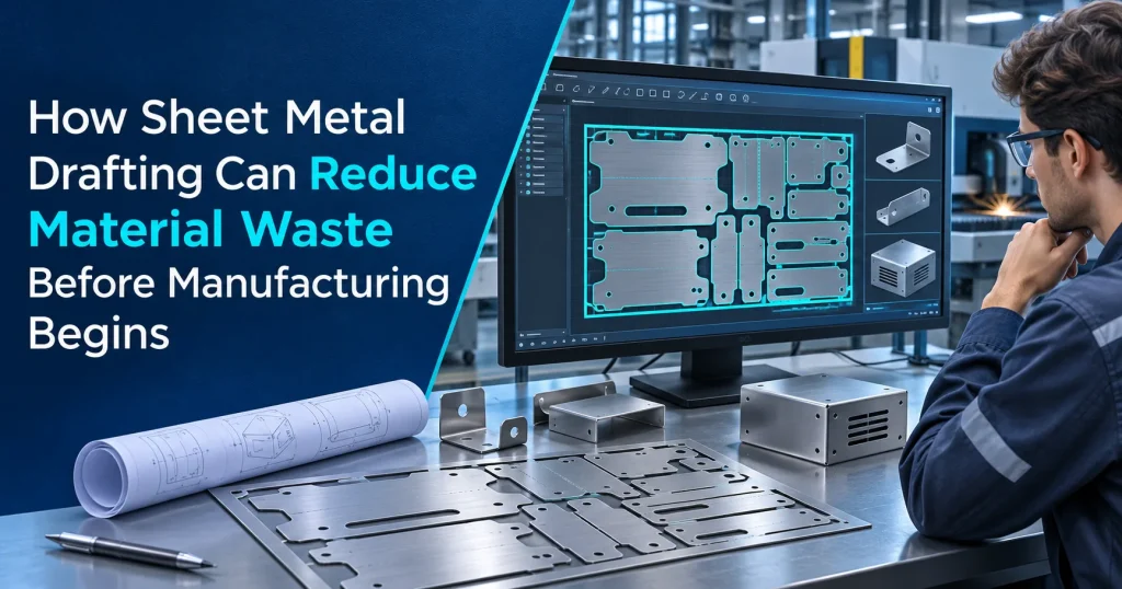
A laser cutter has no opinion about your drawing. It cuts exactly what the file says, at full speed, across a sheet you have already paid for. If the flat pattern is a few millimetres long, if a relief is missing, or if every part is locked to one direction, the machine will still cut them, and the waste is built in before anyone touches a press brake.
That is why the cheapest place to save sheet metal is the drafting desk. This guide follows the path from a 3D part to a nested sheet. It shows where material is lost, how accurate flat patterns and nesting preparation recover it, and how to estimate what better sheet utilisation is worth for your own production.
Most sheet metal scrap is decided before the laser fires. Accurate flat patterns, correct bend allowances and nest-ready part geometry let fabricators fit more parts on every sheet, cut fewer re-makes and keep usable remnants. Good drafting turns waste from a shop-floor surprise into a number you can plan.
Where Sheet Metal Waste Really Starts
Walk past any cutting cell and the waste looks like a shop-floor problem: skeletons stacked by the machine, offcuts in a bin, a pallet of rejected brackets. Yet most of that pile was decided earlier, by the geometry that reached the nesting software.
Some losses are unavoidable. Every sheet has edges the machine cannot use, and every cut removes a thin line of metal as kerf. Other losses are drafting decisions in disguise. Part spacing, part orientation, whether neighbouring parts can share a cut and whether the blank is the right size all trace back to the drawing.
Re-makes
Notice which slices you control. Skeleton size, dead remnants and re-makes together often make up the largest share of avoidable loss, and each one responds directly to better flat patterns and nesting preparation. Edge trim and kerf shrink too, simply because fewer sheets are needed for the same parts.
Flat Patterns: The Drawing the Laser Actually Cuts
Designers think in formed parts: a box, a bracket, a channel. The cutting machine only ever sees the flat pattern, the unfolded outline of that part before any bend is made. Every millimetre of material starts as a feature of that outline.
When metal bends, the outside of the bend stretches and the inside compresses. Somewhere inside the thickness is a neutral axis that keeps its length. A correct flat pattern is measured along that axis, which is why it is always shorter than the sum of the formed outside dimensions. Professional sheet metal design drafting builds this into the model, so the flat pattern is calculated rather than guessed.
In this example the difference is 7.2 mm on a single small channel. Size the blank by adding the sides together and every part comes out long. The holes drift away from their datums, the flanges no longer meet and the batch is scrapped after it has been cut and bent. Multiply that by a production run and a small arithmetic shortcut becomes a skip full of metal.
Bend Allowance: Small Numbers, Big Scrap Piles
The flat pattern depends on three inputs for each bend: the sheet thickness, the inside bend radius and the K-factor. The K-factor describes where the neutral axis sits within the thickness. It is often somewhere between about 0.3 and 0.5, and it changes with material, thickness, tooling and bending method.
This is where many drawing sets go wrong. A CAD template might default to 0.5 while the fabricator’s press brake behaves closer to 0.42. The difference per bend looks tiny. Try it below with your own numbers, and watch how quickly a rounding-level error crosses a typical tolerance once a part has several bends.
BA = π/180 × angle × (R + K × T). The K-factor places the neutral axis inside the thickness. Use the value your press brake shop has tested, not a textbook default.
The fix is not complicated, but it has to happen before cutting. Ask the fabricator for their tested bend table, or bend a test coupon and measure it. Then set that value in the CAD model so every flat pattern is generated the same way. Once the K-factor is right, the flat DXF can go straight to nesting without a trial batch.
Nesting Preparation Starts on the Drafting Desk
Nesting software arranges parts on a sheet to use as much of it as possible. It is powerful, but it can only work with what it receives. Open contours, duplicate lines, unclear part quantities or a grain note on every part all force it into cautious, wasteful layouts.
Nest-ready drafting means each part arrives as a single clean closed contour, with the right quantity, a clear material and thickness, and freedom to rotate wherever the function allows. Below is the same batch of 28 parts, nested three ways on a standard 2500 × 1250 mm sheet.
utilisation
The parts did not change between the three views. What changed was the information that came with them. Allowing rotation, using the cutter’s real minimum spacing and designing straight shared edges for common-line cutting pulled the same batch into a much shorter run of sheet.
Look at the remnant too. A scattered layout leaves narrow strips that end up as scrap. A planned nest leaves one clean rectangle that can go back into stock for the next job. Clear manufacturing and fabrication drawings that list material, gauge and quantities per part make this kind of planning possible across multiple jobs.
Five Drawing Errors That Quietly Waste Sheet
Most wasteful drawings don’t look wrong. They pass a quick visual check, get released and only reveal themselves as torn corners, stretched holes or parts that won’t fit. The bracket below is a typical example. Review each red markup the way a senior checker would.
Waste:
Fix:
Notice that two of the five problems are about information, not geometry. A blanket grain note and a tight tolerance on a free edge both make good parts harder to cut efficiently. Geometric dimensioning and tolerancing solves this by telling the shop exactly which features control fit and function, so everything else can be cut at the machine’s standard accuracy.
Why a Fix on Paper Costs a Fraction of a Fix on the Floor
Every one of these errors can be caught at any stage. The difference is what it costs to catch it. Quality teams often quote the “rule of ten”: a defect costs roughly ten times more to fix at each stage it travels further down the line. Treat the multipliers as a rule of thumb, not a measurement, but the direction is hard to argue with.
—
Based on the widely quoted “rule of ten” for the cost of quality. A rule of thumb, not a measured figure for your shop.
For sheet metal the jump between the second and third stage is the painful one. Up to nesting, a mistake costs only time. Once the sheet is cut, it costs material. Material that has already become a skeleton cannot be recovered, so a drawing check is the last point where waste is still free to remove.
Estimate What Better Sheet Utilisation Is Worth
Utilisation is the share of each sheet that leaves the building as finished parts. Even a few percentage points matter, because material is often the largest single cost in a sheet metal part. Enter your own sheet size, thickness, monthly usage and price to see the material saving from a realistic improvement.
Estimate only. It counts raw material, not the extra cutting time, handling or scrap-sale value. Use your own prices and measured utilisation for a real decision.
The calculator holds your parts output constant and asks how many fewer sheets you would need to make them. The real saving is usually larger. Fewer sheets also mean fewer machine loads, less handling and fewer re-makes, none of which are counted here.
How Microdras Prepares Sheet Metal Drawings for Lean Cutting
Microdras drafts sheet metal parts with the cutting floor in mind. We start from a parametric 3D mechanical model with the bend table and K-factor matched to your fabricator. Flat patterns are generated from that model, never typed in by hand, and every drawing follows ASME, ISO, DIN or BIS conventions as your project requires.
Many projects start with older paperwork rather than a clean model. We can rebuild those parts through paper to CAD conversion, then turn them into nest-ready sheet metal files. Here is what a typical sheet metal package includes.
The Bottom Line
Material waste in sheet metal is rarely a cutting problem. It is usually a drawing problem that reaches the cutting floor. Wrong K-factors produce wrong blanks. Missing reliefs produce torn parts. Rigid grain notes and messy contours produce half-empty sheets and remnants nobody can use.
Fix those issues at the drafting stage and the savings show up before manufacturing begins: more parts per sheet, fewer re-makes, cleaner remnants and production that runs from the first sheet. That is the cheapest material saving a fabrication project will ever get.
Get drawings your nesting software can actually use
Send your models, PDFs, sketches or legacy prints. Microdras returns verified flat patterns, nest-ready DXFs and clear fabrication drawings, so the waste is cut on paper before it reaches the sheet.
FOR CUTTING
Frequently Asked Questions
Drafting sets the size and shape of every blank before it is cut. Accurate flat patterns prevent re-makes, reliefs and correct hole positions stop parts failing after bending, and nest-ready geometry lets nesting software fit more parts on each sheet. Together these cut scrap before manufacturing begins, which is cheaper than finding it on the shop floor.
A flat pattern is the unfolded 2D outline of a sheet metal part, the shape the laser, punch or plasma cutter actually cuts. It accounts for how metal stretches and compresses in each bend. If it is wrong, every part in the batch comes out the wrong size after forming.
There is no universal value. K-factors often fall between about 0.3 and 0.5 and depend on material, thickness, bend radius, tooling and bending method. The most accurate approach is to use your fabricator’s tested bend table, or to bend and measure a test piece, then set that value in the CAD model.
Nesting software can only optimise what it receives. Open contours, duplicate lines, unclear quantities and unnecessary grain-direction notes force cautious layouts and lower utilisation. Clean, closed flat-pattern DXFs with clear material data and rotation freedom let the software produce much tighter nests.
Yes. Microdras can convert paper prints, PDFs or 2D CAD into 3D sheet metal models, then generate verified flat patterns, nest-ready DXF files and fabrication drawings. You can share your files for an estimate, and the team replies to every enquiry within 24 hours.
